|
Museo Didattico di Storia dell' Informatica Padova, Italy |
Computer-Cabinett-Göttingen e.V. Göttingen, Germany You might look at the current project. |
Padua, June 2000
While going on we were able to learn much about IBM's philosophy. We gained historic insight in construction tecniques and service staff training. A most striking result was that the service manuals contain very little information as to how the circuits work. In spite of their impressive dimension (over 800 A3 pages) they are limited to replacement rules for entire subassemblies.
The floppy disk drives (model 33FD) are of historic importance: first introduced with the IBM 3740 family, they were the industry standard of which many elements remain in today's omnipresent 3 1/2 inch floppy disk technology. We used a nice experimental setup that may be used in any computer exhibition to explain principles of magnetic storage.
IBM-Baby 3741
MÜNCHEN - Die Modelle 3 und 4 des IBM-Systems 3741 werden zunehmend als Stand-alone-Computer eingesetzt. Ursprünglich als Datenerfassungsgerät mit Diskette angeboten, reden neuere IBM-Prospekte von der "Datenverarbeitungsstation" 3741. Mit 8 K Bytes und Anschluß eines Matrixdruckers kostet das IBM-Kleinsystem rund 1500 Mark Monatsmiete. Das System /32 beginnt erst bei 2230 Mark monatlich. os
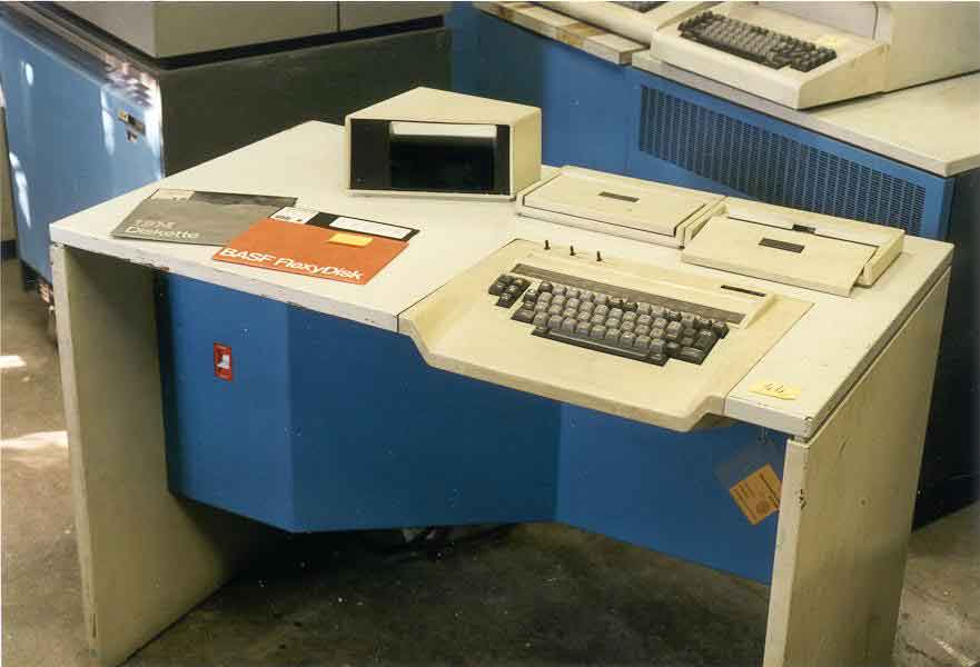 Our specimen was delivered on 18 August 1977
and features an Italian keyboard layout. The machine at Padua has two disk
drives and a serial modem built in. 2 kb of RAM are installed.
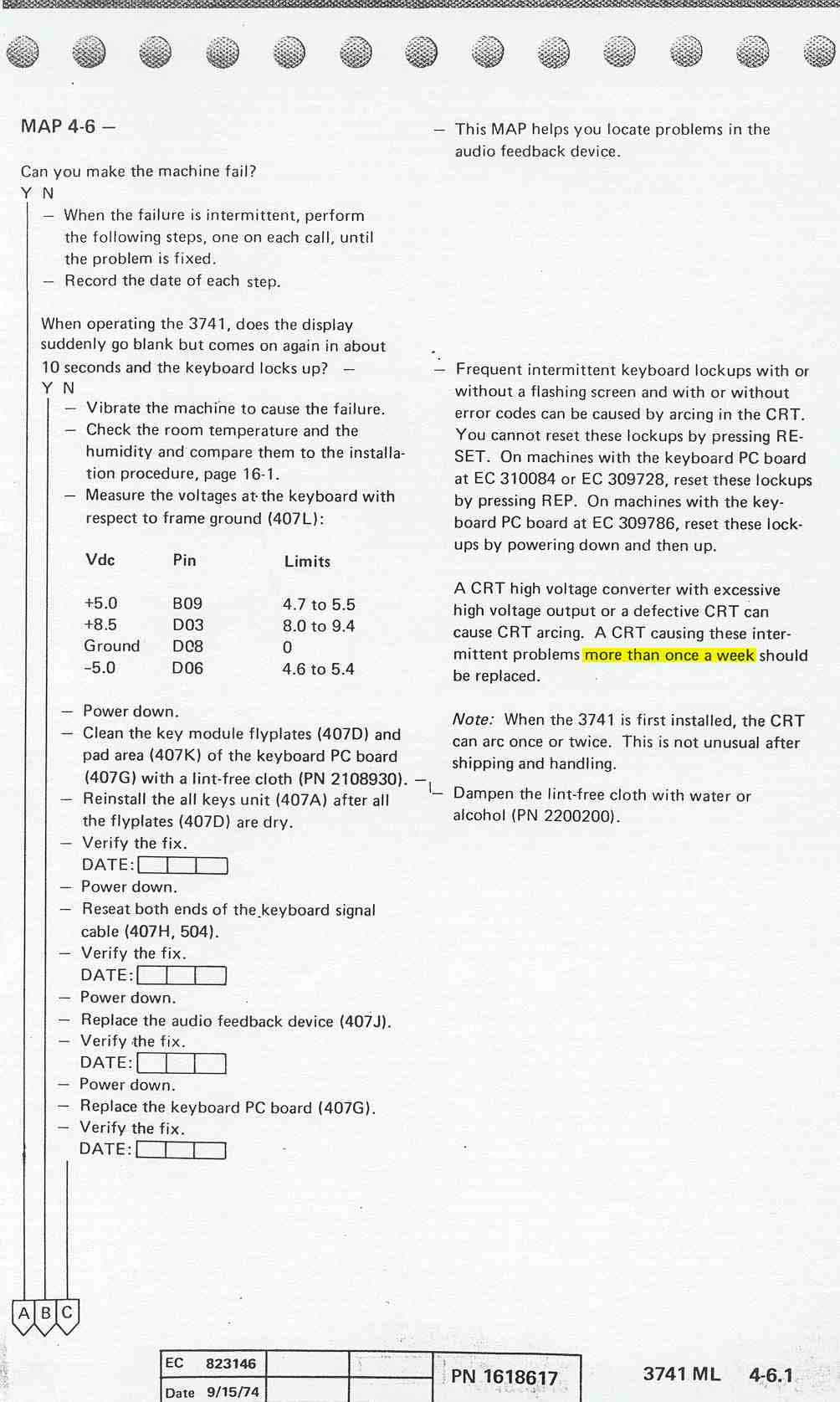
As an example, look at Error Map 4-6. You normally get here when the buzzer either remains silent or is always on (as in our case when the reset process later gave out). Note the tolerances!

IBM customers must not have been very demanding: in Map 5-1.2 it reads
Do extra characters still appear when the diskette is loaded?
If this symptom is a customer complaint, replace the failing PC board. This symptom does not affect machine functions.
 Electrolytic
capacitors age. Especially the ones that IBM used (non standard, of course)
don't stand 12 Volts any more after 23 years. So when we turned on the
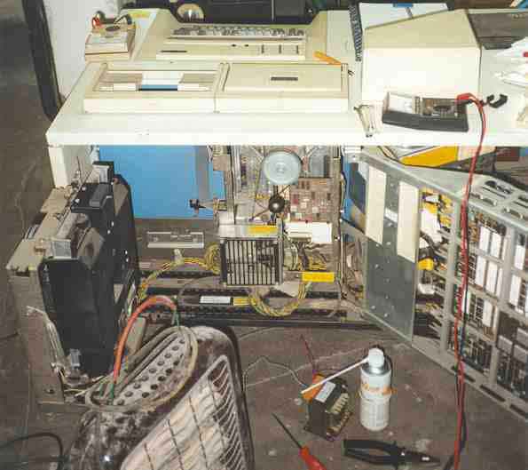
machine, we short-circuited both CRTs. The reason that we blew only one
capacitor and that we found it is that it was used as a power line bypass, with
the full potential across it. Capacitors from timing circuits often are
exposed to less voltage. Of course nobody had ever seen a capacitor like
that (or have you?), and we could neither measure the capacity any more
nor guess it from the stamped code (2391 268 1629). I heard that even the
IBM Pensioneers Club does not have access to IBM's internal conversion
charts.
Addendum 17. Dec. 2000 I learned from Henk Stegeman, who owns an IBM 3741 himself and is lucky to have pieces of the 'internal use only' documentation, that IBM P/N 2391268 is a tantaal, 6.8 µF, 20Volt.
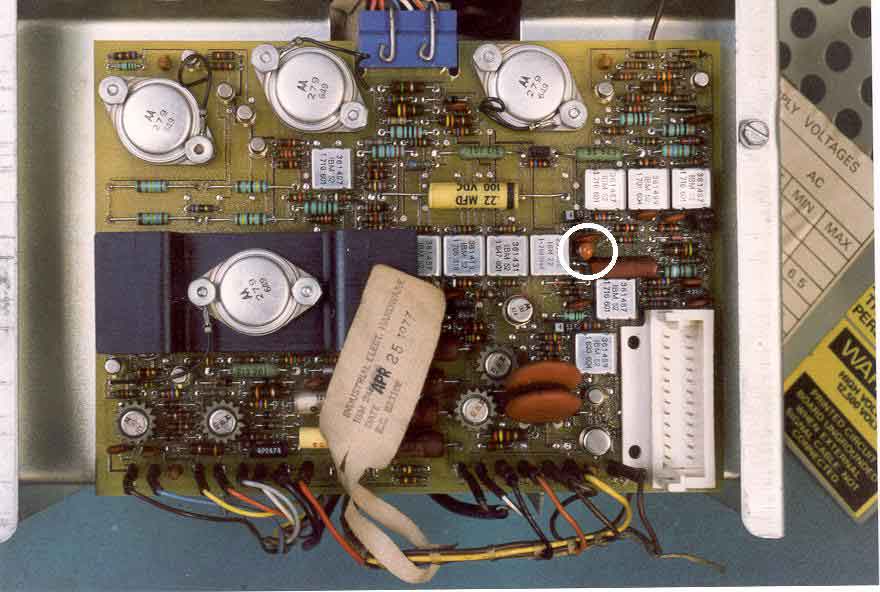
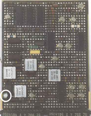
Normally, the CRT should work without bypass capacitors. To be on
the safe side we put a 10µF 16V tantalum capacitor
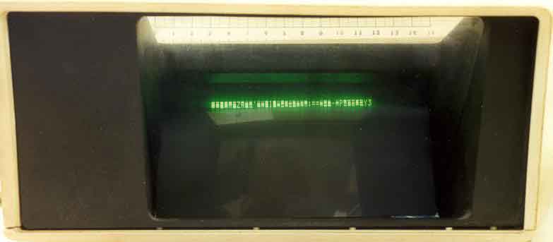
(white circle). On 20 June 2000 at 18:15, we turned it all on and... 25
seconds later we saw the status line appear on the screen. It worked!
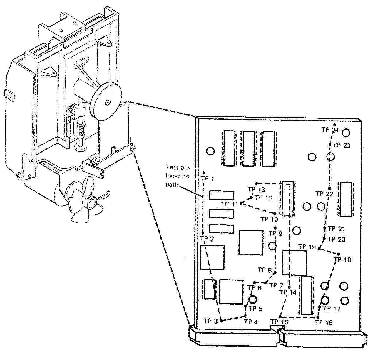
| FC Card
Test Point |
Test Pin Name |
| TP 1
TP 2 TP 3 |
+24 volts
+ Index + File data |
| TP 4
TP 5 TP 6 |
+ Access 2
-5 volts + Access 3 |
| TP 7
TP 8 TP 9 |
+ Access 1
Phototransistor + Write data |
| TP 10
TP 11 TP 12 |
+ Head engage
+ Low current + Write gate |
| None
TP 13 TP 14 |
+ Erase gate
Preamp TP 2 Preamp TP 1 |
| TP 15
TP 16 TP 17 |
+ Access 0
LED current Ground |
| TP 18
TP 19 TP 20 |
- MC-0
- MC-3 - MC-2 |
| TP 21
TP 22 TP 23 |
- MC-1
- Head load +5 volts |
| TP 24
None None |
Erase current
Head A Head B |
 We
found that 24V at TP 1 were missing, even though they were present at the
main board. Moreover, the corresponding capacitor (!) was short-circuited.
So that's where the burnt smell came from a week ago! Instead of blowing
the 8A fuse in the 24V line, some circuit traces on the printed boards
had burnt. They are much thinner than the fuse and extremely difficult
to find and repair. A clear design flaw by IBM.
Luckily, we could borrow a 33FD drive FC
card from an IBM 2502 Punch Card Reader, that's why we keep junk. We soldered
out the critical capacitor before power-on this time. It had some
700 nF (code 2414 883 L646), so we chose new 1 µF electrolytic
capacitors for replacement (sponsored by Grundig). I don't know how the
capacity may have changed with age.
After re-installation the supply voltages remained constant, but we still could not read from disk.
Obviously, a constant power supply voltage with no oscillations or
spikes is important for any circuit's function. At high frequencies
the power supply's feedback regulator may not cope, so it helps to
reduce line impedance. To achieve this, power supply leads are
bypassed to ground throughout a circuit, using a combination of
ceramic (0.01-0.1 µF) and electrolytic (1-10 µF) capacitors.
In computer restoration we deal with digital circuits where many logic
lines may switch simultaneously. A digital output, for example, that
drives three
address decoders, sees an input capacitance of up to 50pF, depending
on the chips and their connections. If the transition happens in
0.6ns, the current will be 40mA. With a wiring inductance of 5nH/cm we
easily arrive at a spike of half a Volt on the power or ground line
when the chip's lead is long. (see Horowitz, Hill, The Art of
Electronics, 2nd Ed., ch. 9.12) The faster the edge
transitions are and the more lines are switched, the more important
are functioning bypass capacitors.
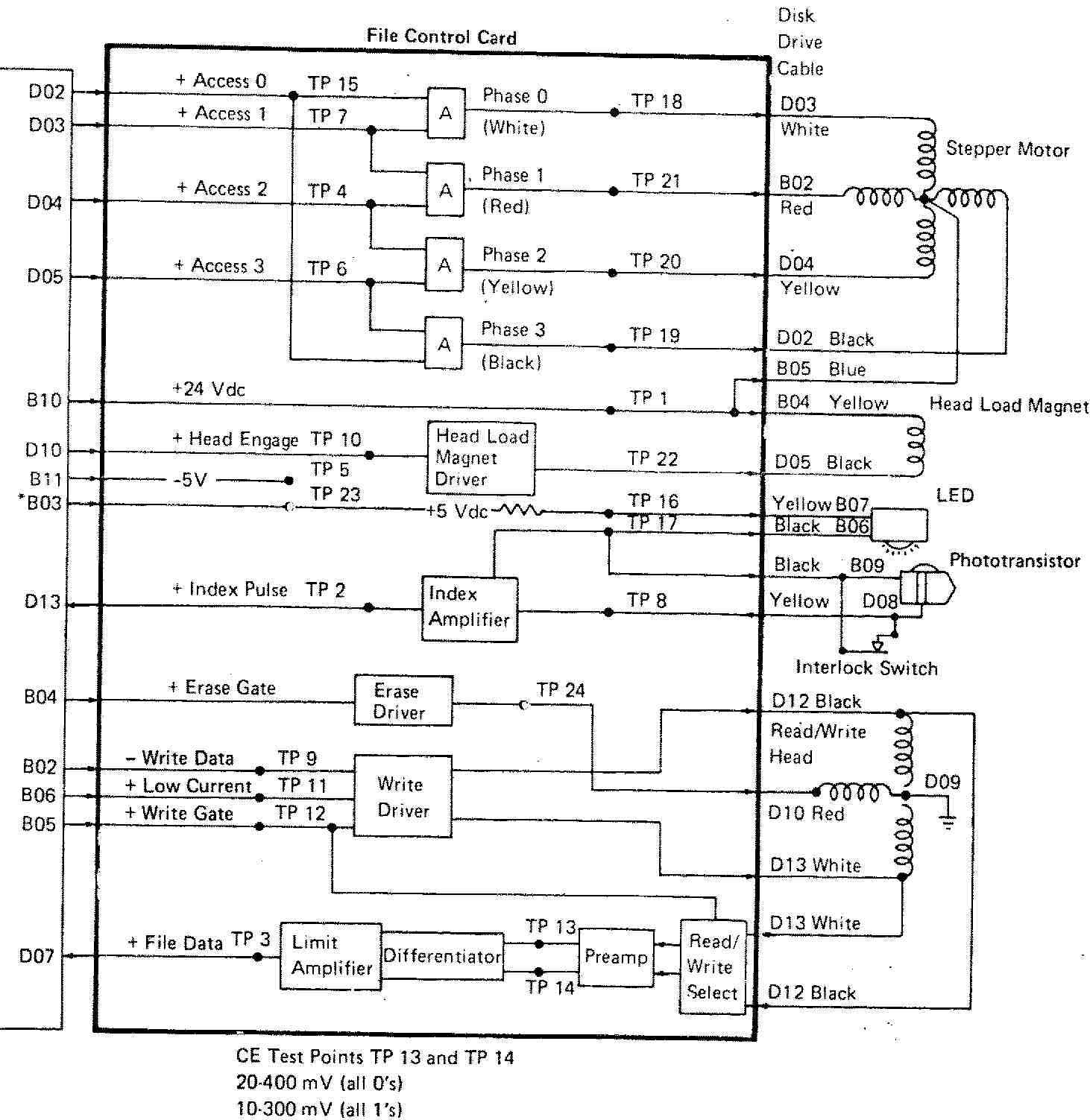
The disk is divided into 77 tracks, numbered from 00 at the outside to 76 at the center. They are addressed by movement of the head, effected by a unipolar stepper motor. 90° turn of the screw correspond to 1 track. It is notable that at least two defective tracks can be marked and will be left out automatically, so there are always 75 working tracks. The angular beginning of the tracks is marked by an index hole in the disk which is optically recognized. This is all the FC card does, and with the diagram from the manual, the individual functions can be traced to the test points.
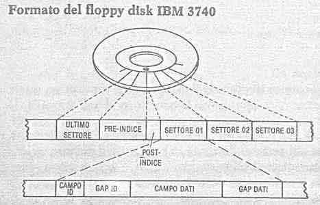
Note the relation between sector sequence
and index hole as shown in the graph. We were able to observe directly
ID and data fields and gaps. The gap lengths are:
| gap | length (byte) |
| post-index | 22 |
| ID | 17 |
| data | 33 |
| pre-index | ca. 230, depends on physical track length |
The following format details cannot be observed directly but are included for completeness:
In our case, every bit cell is 4 µs long and has a clock pulse at the beginning. To represent logical 1, another pulse is set at the middle of the cell. In the case of zero, there is nothing until the next cell's clock. For double density, a reduction of cell length to 2 µs is achieved by writing the clock pulse only if both the preceding and the actual cell are logical 0.
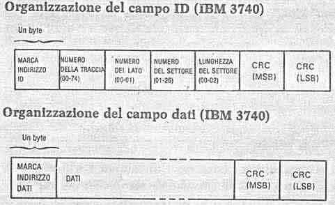 The
ID field consists of a specific one-byte address mark and six more bytes.
They contain the track no., the disk side no., the sector no. and a code
for the sector length (00, 01, 02 for 128, 256, 512 Byte). Bad tracks are
marked by setting these Bytes to FF. At the end the ID field contains MSB
and LSB of the data checksum.
The
ID field consists of a specific one-byte address mark and six more bytes.
They contain the track no., the disk side no., the sector no. and a code
for the sector length (00, 01, 02 for 128, 256, 512 Byte). Bad tracks are
marked by setting these Bytes to FF. At the end the ID field contains MSB
and LSB of the data checksum.
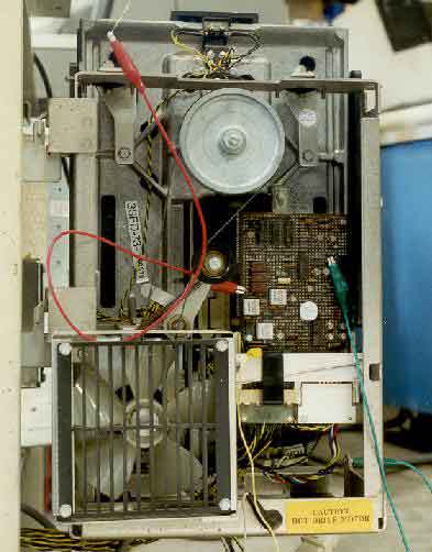 |
With a rather simple installation the
confusing data format can be displayed very clearly. At TP 3, the FC card
of the drive provides the digital data of about 1V Amplitude (yellow wire).
All we had to is to display it on an oscilloscope. To hold the sectors
in place on our screen, we used as external trigger the prepared pulse
at TP 2 which contains the optical information from the diskette index
hole (red wire). In order to get nice signals, the head load magnet had
to be switched on, we connected TP 22 to frame ground (green wire).
There is one problem: because of the relatively
low disk speed, we get only 60 Hz for our signal. On modern high speed
oscilloscopes the screen is sometimes not phosphorescent enough to give
sufficient brightness at low frequencies. Of course Francesco had a historic
15 MHz oscilloscope with tubes!
|
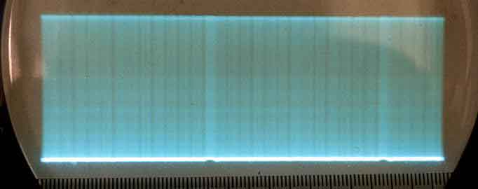
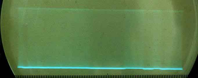
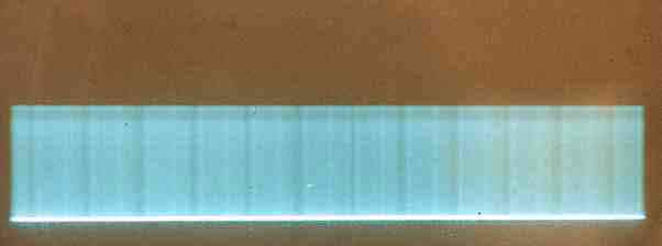
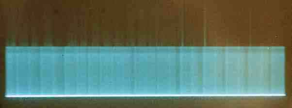
Here it is! What you see is a bit more
than one track, the gaps between sectors showing as dark vertical lines
(left picture). If we zoom onto one sector, we loose a lot of brightness.
The data gap of the first and the ID gap of the following sector can yet
be seen (to the right).
 |
 |
How far can this go? We don't expect to see single bits. The brightness would be insufficient, and also the index pulse trigger is probably not precise enough to synchronize the 4 µs cells. But let's try. The next image represents about one tenth of a sector, with the timescale set to 8 µs /cm. Indeed, we see a periodic signal with ten periods on 6.4 cm, corresponding to 5.1 µs each. Are these bit cells or not ?!

Head position adjusted |
Head between two tracks |
What did we learn? The next time one plans to power up an IBM machine after over 20 years, it's advisable to
a) disconnect everything from the power supply at first and to proceed step by step and
b) solder out a bypass capacitor from the supply lines, at least at 12V and 24V, and try it at some overvoltage. (After measuring its capacity.)
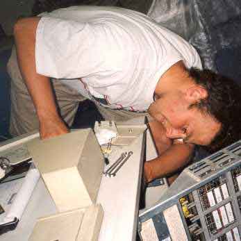
Martin Wölz |
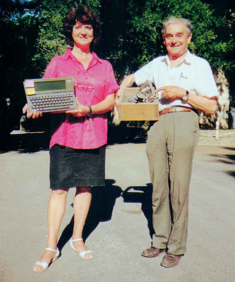
Silvia Basaldella, Francesco Piva |
We had a great time and hope to have given
some ideas. You might look at the current project.